

This article is based on practical experience from a 10 ton heavy duty AGV project undertaken by Plutools. It covers the key considerations in traction and power calculations, differential drive wheel selection, the decision to replace ball screw lifting with hydraulic lifting, and several typical issues encountered during commissioning. It is intended as a technical reference for engineers and developers working on heavy duty AGV systems.
1. Project Overview
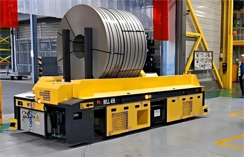
We received a project requirement from a heavy machinery manufacturer to develop a heavy duty AGV with a rated payload of 10 tons. The AGV would be used for flexible transportation of large structural components between the welding and machining workshops.
The customer's original solution was a rail guided vehicle. Although this solution was relatively simple, its route was fixed and it could not avoid obstacles. Manual assistance was also required whenever the vehicle needed to dock with a workstation, resulting in low overall efficiency.
The customer wanted the new AGV to provide flexible omnidirectional transportation, with a docking accuracy of plus or minus 1 mm to support automatic loading and unloading.
Initial Design Parameters
| Parameter | Symbol | Value | Unit | Remarks |
|---|---|---|---|---|
| Rated payload | m_load | 10000 | kg | Specified by customer |
| Vehicle weight | m_body | 3500 | kg | Including frame, battery and electrical system |
| Total mass at full load | m | 13500 | kg | Full load condition |
| Vehicle dimensions | L x W x H | 4000 x 1480 x 400 | mm | Subject to final design |
| Maximum travel speed | v_max | 30 | m/min | Indoor transportation |
| Target docking accuracy | - | plus or minus 1 | mm | Customer requirement |
| Maximum gradeability | i | 2 | percent | Indoor factory floor |
| Acceleration time | t_acc | 3 | s | 0 to maximum speed |
| Floor condition | - | Epoxy floor | - | Rolling resistance coefficient 0.015 |
The vehicle height was limited to 400 mm, which is relatively low for a heavy duty AGV of this capacity.
There were two main reasons for this design. First, some workstations in the customer's facility had maintenance platforms underneath them, resulting in limited clearance. Second, a lower center of gravity helps improve vehicle stability when transporting 10 ton loads.
2. Drive System Selection: Why Use a Differential Drive Wheel?
During the design stage, we compared two drive system approaches.
Option A: Distributed Drive System
This solution consists of separately selected and assembled motors, gearboxes and drive wheels.
Advantages:
Flexible component selection
Individual components can be replaced independently
Disadvantages:
Difficult to control accumulated assembly errors
Motor shaft and gearbox input shaft alignment require careful adjustment
Gearbox output shaft and wheel shaft alignment also require on site adjustment
Maintenance requires coordination with multiple suppliers
Option B: Integrated Differential Drive Wheel
The integrated solution combines the travel motors, gearboxes, drive wheels and encoders into a single drive wheel assembly.
Advantages:
The complete transmission chain is assembled and calibrated before delivery
On site installation mainly involves mechanical mounting and electrical connections
Compact structure saves valuable chassis space
Reduces on site alignment and commissioning work
Disadvantage:
More parameters need to be finalized during the initial selection stage, leaving less room for later modifications
Considering the customer's plus or minus 1 mm docking accuracy requirement, achieving the same level of precision with a distributed drive system would require significant on site alignment and commissioning.
We therefore recommended the integrated solution.
The final design used two sets of Plutools TEC 240 heavy duty differential drive wheels, with a rated load capacity of 4000 kg per set. The two drive wheel sets were arranged in parallel to support the vehicle. Considering the total loaded vehicle mass of 13.5 tons, sufficient capacity margin was also maintained.
Key Specifications of the TEC 240 Differential Drive Wheel
| Item | Specification |
|---|---|
| Wheel diameter | 240 mm |
| Rated load per set | 4000 kg |
| Drive motors | 2 Plutools TEC permanent magnet servo motors per set |
| Rated motor power | 750 W per motor |
| Rated motor torque | 2.4 N m per motor |
| Rated voltage | 48 V DC |
| Integrated gear ratio | Approximately 40:1 |
| Encoder | Absolute encoder with dual channel feedback |
| IP rating | IP65 |
3. Traction and Power Verification
3.1 Resistance Calculation
Rolling resistance:
F_roll = m x g x mu
= 13500 x 9.81 x 0.015
= 1986.5 N
Grade resistance at a 2 percent slope:
F_slope = m x g x i
= 13500 x 9.81 x 0.02
= 2648.7 N
Acceleration:
a = (30 / 60) / 3
= 0.1667 m/s2
Acceleration resistance:
F_acc = m x a
= 13500 x 0.1667
= 2250 N
Peak total traction force under the most demanding condition, with acceleration and climbing occurring simultaneously:
F_total = F_roll + F_slope + F_acc
= 1986.5 + 2648.7 + 2250
= 6885.2 N
For normal operation on a level floor at constant speed:
F_steady = F_roll
= 1986.5 N
3.2 Power Verification
Assuming a transmission efficiency of 85 percent, the required peak drive power is:
P_peak = (F_total x v_max) / eta
= (6885.2 x 0.5) / 0.85
= 4050 W
= 4.05 kW
The maximum speed is:
v_max = 30 m/min = 0.5 m/s
Each TEC 240 differential drive wheel set is equipped with two 750 W Plutools TEC permanent magnet servo motors, providing 1.5 kW per drive wheel set and 3.0 kW continuous power for the two sets combined.
Considering the short term overload capability of servo motors, which can typically reach 2 to 3 times the rated output, the available peak output is sufficient to cover the calculated 4.05 kW requirement.
In the actual project, we also implemented current limiting through the servo drives. The peak power of each drive wheel set was limited to approximately 2.2 kW, providing additional protection and operating margin.
3.3 Traction and Wheel Slip Verification
Another important step is to verify that the drive wheels will not slip during heavy load acceleration or uphill operation.
The two TEC 240 differential drive wheel sets provide a total of four drive wheels.
For heavy duty AGVs, the drive wheels typically carry approximately 60 percent of the total vehicle weight, with the remaining 40 percent supported by idle wheels.
The vertical load on each drive wheel is therefore:
W_wheel = (13500 x 9.81 x 0.6) / 4
= 19865 N
For PU wheels running on an epoxy floor, the traction coefficient is typically around 0.5 to 0.7. We used a relatively conservative value of 0.6 for the calculation.
The maximum available traction force per wheel is:
F_max = W_wheel x mu_att
= 19865 x 0.6
= 11919 N
The actual traction force required per wheel under the most demanding condition is:
F_wheel = F_total / 4
= 6885.2 / 4
= 1721.3 N
Therefore:
11919 N is much greater than 1721.3 N
The calculated traction margin is close to seven times the required force.
This provides a substantial margin against wheel slip. The actual project also confirmed the calculation. Even when the workshop floor had just been cleaned and was still relatively wet, the fully loaded AGV was able to start smoothly without noticeable wheel slip.
4. Lifting System: Why Replace Ball Screws with Hydraulic Lifting?
The customer's original concept used an electric ball screw lifting system. Four SFU4010 ball screws were arranged at the four corners, with each screw driven by a servo motor, gearbox and brake.
During the design review, we recommended replacing this solution with a hydraulic lifting system integrated into the differential drive wheels.
The main reasons were as follows.
| Comparison | Ball Screw Lifting | Integrated Hydraulic Lifting |
|---|---|---|
| Mechanical components | 4 ball screws, 4 nuts, 4 support assemblies, 4 couplings, 4 motors and 4 gearboxes | Hydraulic power unit, valve block and hydraulic cylinders integrated into the drive wheel assemblies |
| Synchronization | Requires electronic cam synchronization of four axes, resulting in more complex control logic | Hydraulic flow divider provides inherent synchronization and simplifies control |
| Anti drop protection | Relies on motor brakes. Long term load holding requires additional consideration | Hydraulic locks and counterbalance valves provide reliable load holding |
| Installation space | Four corners must be reserved for screw installation | Lifting points are integrated into the drive wheel assemblies, reducing additional chassis space |
| Maintenance | Ball screws require regular lubrication and dust protection | Sealed hydraulic system with relatively long maintenance intervals |
The customer ultimately accepted the hydraulic solution.
In actual operation, the lifting speed was approximately 5 mm/s, with a 100 mm lifting stroke taking about 20 seconds. The hydraulic system provided smooth movement and avoided the stick slip behavior that can occur with ball screws under low speed and high load conditions.
Lifting Force and Cylinder Diameter Calculation
The required total lifting force was calculated based on the 10 ton payload:
F_lift = m_load x g
= 10000 x 9.81
= 98100 N
With four lifting points:
F_point = F_lift / 4
= 98100 / 4
= 24525 N
Assuming a hydraulic system pressure of 18 MPa, the theoretical cylinder area required at each lifting point is:
A = F_point / P
= 24525 / 18
= 1362.5 mm2
The theoretical cylinder diameter is:
d = 2 x sqrt(A / pi)
= 2 x sqrt(1362.5 / 3.14)
= 41.7 mm
A cylinder with a theoretical diameter of approximately 42 mm would therefore be sufficient under ideal conditions.
However, we selected an 80 mm cylinder to provide additional capacity and accommodate load imbalance and pressure losses.
With an 80 mm cylinder, the theoretical pressure required for the nominal load is:
P_actual = F_point / (pi x (80 / 2)2)
= 24525 / 5024
= 4.88 MPa
Considering hydraulic line losses and uneven load distribution, the final system pressure was set to 12 MPa.
The lower operating pressure reduces heat generation and leakage risk while also helping extend the service life of the hydraulic seals.
5. Electrical Control and Battery Configuration
5.1 Battery Capacity
The theoretical peak total power consumption, assuming travel and lifting occur simultaneously under extreme conditions, is:
P_total = 4.05 + 0.7
= 4.75 kW
In actual operation, the AGV rarely operates the travel and lifting systems at full load simultaneously.
Assuming an overall duty cycle of 40 percent, the estimated average power consumption is:
P_avg = P_total x 0.4
= 4.75 x 0.4
= 1.9 kW
The system uses a 48 V power platform.
The estimated average current is:
I_avg = P_avg / U
= 1900 / 48
= 39.6 A
For an 8 hour operating period and an 80 percent depth of discharge:
C = I_avg x t / DOD
= 39.6 x 8 / 0.8
= 396 Ah
The final configuration used a 48 V / 400 Ah lithium iron phosphate battery pack.
Under a fully loaded continuous transportation cycle, the actual endurance test reached approximately 7.5 hours, which was close to the target requirement.
If longer operating time is required in the future, the system can be upgraded with a second battery pack or an automatic battery changing station.
5.2 Drive Control System
Each TEC 240 differential drive wheel set is equipped with two matching Plutools TEC servo drives using EtherCAT communication.
A total of four servo drives communicate with the main PLC through EtherCAT, with a synchronization cycle of 1 ms.
The main controller selected for the project was a Beckhoff CX5140, mainly because of its EtherCAT master performance and extensive motion control functions.
One of the key challenges during commissioning was wheel speed matching during differential steering.
Since the two differential drive wheel sets are positioned at the front and rear of the vehicle, their instantaneous linear speeds are different when the AGV turns. The required wheel speeds must therefore be calculated according to the turning radius and vehicle geometry.
We implemented a kinematic model in the PLC and converted the steering command into independent speed commands for the four drive wheels.
After adjustment, the AGV showed no significant wheel drag or lateral slip during turning.
6. Lessons Learned from the Project
1. The Advantages of Differential Drive Wheels Are More Significant in Heavy Duty Applications
We had previously used distributed drive systems in many projects. One of the biggest advantages we experienced with the integrated differential drive wheel solution was the significant reduction in on site commissioning time.
With a conventional distributed system, one to two weeks may be required to adjust transmission alignment and gear engagement. In this project, the TEC drive wheel assemblies could be installed with bolts and connected to the power and encoder cables immediately after delivery.
The basic travel commissioning was completed in approximately three days.
2. Hydraulic Lifting Provided Better Stability Than the Ball Screw Solution
Under low speed and high force operating conditions, ball screws can experience stick slip behavior, particularly when the load is unevenly distributed.
The hydraulic lifting system provides smooth force output and avoids this issue.
The customer reported that the platform remained stable during fully loaded lifting operations, allowing the AGV to complete docking without repeated manual adjustments.
3. Practical Safety Margins Matter More Than Theoretical Calculations
The resistance calculations were based on relatively ideal floor conditions. In a real factory, however, the floor may have oil contamination, joints, small uneven areas or temporary changes in surface conditions.
For this reason, we maintained relatively large margins in both drive power and traction during the final selection.
This proved useful in actual operation. On one occasion, the floor had just undergone maintenance and was not completely dry. The fully loaded AGV was still able to start and accelerate normally without triggering a wheel slip alarm.
4. A 48 V Power Platform Is Sufficient for a 10 Ton AGV
At the beginning of the project, the customer was concerned about whether a 48 V system could provide sufficient power for a 10 ton AGV.
Actual operation demonstrated that the current remained within a reasonable range, with a peak current of approximately 120 A and a continuous current of around 40 A.
A 48 V system also provides several practical advantages. Batteries, cables, contactors and other electrical components are widely available, system costs can be controlled, and maintenance is relatively straightforward.
5. Pay Close Attention to Load Distribution on Idle Wheels
This was one of the issues discovered during the later stages of the project.
The initial design used four idle wheels. During testing, however, we found that the limited rigidity of the chassis caused uneven load distribution among the idle wheels. Several individual wheels were overloaded and produced abnormal noise.
We subsequently increased the number of idle wheels to six and added a balancing swing beam structure.
The problem was resolved after the modification.
For similar heavy duty AGV projects, we recommend considering a six idle wheel configuration at an early design stage and reserving a suitable wheel load adjustment mechanism in the chassis design.
Conclusion
For a 10 ton class heavy duty AGV, the drive system is not simply a matter of selecting motors with sufficient power. The complete system must be evaluated together, including traction, load distribution, wheel configuration, lifting mechanism, control synchronization, battery capacity and real world floor conditions.
In this project, the combination of integrated differential drive wheels, hydraulic lifting, EtherCAT based motion control and a 48 V electrical platform provided a practical balance between load capacity, positioning accuracy, system stability and maintainability.
More importantly, the project demonstrated that the performance of a heavy duty AGV depends not only on theoretical calculations, but also on the engineering margins built into the design and the details addressed during actual commissioning.


