

If the power battery is the "blood reservoir" of an electric vehicle, the drive motor is the tireless "pump" that converts electrical energy into mechanical power and ultimately drives the wheels forward. Compared with traditional internal combustion engines, electric drive motors offer high efficiency, high power density, quiet operation, and zero tailpipe emissions, making them one of the most important components of modern electric mobility.
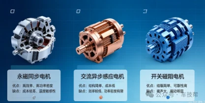
1. Three Main Types of Drive Motors, Each with Its Own Strengths
Today, three major motor technologies are widely used in new energy passenger and commercial vehicles.

1. Permanent Magnet Synchronous Motor (PMSM) - The Efficiency Leader
Structure: The rotor incorporates rare-earth permanent magnets such as NdFeB, while the stator consists of three-phase windings.
Operating Principle: Three-phase AC power supplied to the stator generates a rotating magnetic field. This field interacts with the magnetic field of the permanent magnets on the rotor to generate electromagnetic torque, causing the rotor to rotate synchronously with the magnetic field.
Advantages: Peak efficiency can exceed 95%, with excellent power density, compact dimensions, and precise speed control.
Limitations: Rare-earth materials increase costs, permanent magnets may face demagnetization risks at high temperatures, and high-speed field-weakening control is relatively complex.
Typical Applications: BYD Qin and Han, Tesla Model 3/Y rear-wheel-drive versions, NIO, XPeng, and other electric vehicles.
Working Principle: When three-phase AC power is applied to the stator windings, a rotating magnetic field is generated in the stator core. The magnetic field produced by the rotor's permanent magnets interacts with the stator field to generate electromagnetic torque and drive the rotor.
2. AC Induction Motor (IM) - Rugged and Reliable
Structure: The stator uses three-phase windings, while the rotor consists of squirrel-cage aluminum or copper bars and contains no permanent magnets.
Operating Principle: The rotating magnetic field generated by the stator induces current in the rotor bars. The resulting magnetic field interacts with the stator field to generate torque. The rotor always rotates slightly below synchronous speed, a phenomenon known as "slip."
Advantages: Simple construction, relatively low manufacturing cost, high reliability, and excellent high-speed performance without the risk of permanent-magnet demagnetization.
Limitations: Lower efficiency under light-load conditions, lower power density than PMSMs, and a relatively larger overall size.
Typical Applications: Tesla Model S/X and selected dual-motor configurations of the Model 3/Y.
3. Switched Reluctance Motor (SRM) - Simple by Design
Structure: Both the stator and rotor are made of salient-pole iron cores. The rotor contains neither windings nor permanent magnets.
Operating Principle: Based on the principle that magnetic flux tends to follow the path of minimum reluctance, the stator windings are energized sequentially to attract the rotor poles into alignment, producing continuous rotation.
Advantages: Extremely simple structure, low manufacturing cost, high-temperature resistance, and high starting torque.
Limitations: Significant torque ripple can result in noise and vibration. The control system is relatively complex, while overall efficiency is generally moderate.
Applications: Used in selected commercial vehicles, buses, and specialized applications.
2. A Key Component in the High-Voltage Powertrain
In a typical high-voltage electrical architecture, the drive motor sits at the core of the power transmission chain:
Power Battery (High-Voltage DC) → Power Distribution Unit (PDU) → Motor Control Unit (MCU, DC to Three-Phase AC) → Drive Motor (Electrical to Mechanical Energy) → Reducer (Speed Reduction & Torque Increase) → Wheels
The MCU acts much like a "conductor," precisely regulating voltage, frequency, and phase to achieve real-time control of motor speed and torque.
3. Three Main Motor Installation Configurations
Central-Mounted Configuration
The motor is positioned at the center of the axle and drives both wheels through a driveshaft and/or reduction gear. This configuration offers a mature structure and favorable cost, making it a mainstream solution for many electric vehicles.
Wheel-End Configuration
Two motors are installed at the two ends of the axle, with each motor driving its corresponding wheel through a reduction mechanism. This configuration provides greater flexibility in chassis layout and can be used in various rear-wheel-drive applications.
In-Wheel Configuration
The motor is integrated directly into the wheel hub, minimizing the mechanical transmission chain and potentially improving transmission efficiency. However, the increased unsprung mass can affect handling and ride comfort, which currently limits its widespread application.
4. Demanding Performance Requirements
Electric vehicles place demanding requirements on drive motors:
High Power Density - Delivering high output from a compact package.
Wide Speed Range - Providing high torque at low speeds while maintaining constant-power operation at high speeds.
High Efficiency Across a Wide Operating Range - Maintaining high efficiency under common operating conditions.
High Reliability - Withstanding vibration, temperature variations, and long-term operation.
Low Noise and Vibration - Contributing to a quieter and more comfortable driving environment.
Effective Thermal Management - Using water- or oil-cooling systems to efficiently dissipate heat.
5. Quick Comparison of the Three Motor Technologies
| Performance | PMSM | AC Induction Motor | SRM |
|---|---|---|---|
| Efficiency | ★★★★★ | ★★★☆ | ★★★★ |
| Power Density | ★★★★★ | ★★★ | ★★★★ |
| Cost | ★★★ | ★★★★ | ★★★★★ |
| Reliability | ★★★★ | ★★★★★ | ★★★★★ |
| Control Complexity | ★★★★ | ★★★ | ★★★★★ |
Summary: Thanks to its excellent efficiency and power density, the permanent magnet synchronous motor remains a dominant choice for passenger EVs. Induction motors, with their advantages in cost and reliability, are often used as auxiliary motors in dual-motor all-wheel-drive configurations. Switched reluctance motors, meanwhile, continue to find opportunities in selected commercial vehicle and specialized applications.
6. From Automotive Drive Systems to Industrial Mobile Robots
The underlying technologies of electric drive systems are not limited to automotive applications. Core technologies such as Field-Oriented Control (FOC), Space Vector Pulse Width Modulation (SVPWM), field-weakening control, thermal management, and electromagnetic compatibility (EMC) are equally important in industrial mobile robotics.
In AGVs and AMRs, AGV drive wheels, low-voltage servo motors, and electric drive axles face many of the same engineering challenges found in automotive electric drive systems, including efficiency optimization, torque density, thermal management, motion control, and long-term reliability.
At Plutools, our technical development focuses on these common challenges in electric drive and motion-control applications. Our AGV drive wheels, low-voltage servo systems, and electric drive axle solutions are designed with a strong focus on structural integration, efficient heat dissipation, precise motion control, and reliable operation.
Although automotive drive motors and industrial mobile robot drive systems serve different applications, their underlying engineering logic is closely related. Advances in motor control, power electronics, thermal management, and mechanical integration continue to create new possibilities for both fields.
For engineers and technical professionals working with AGVs, AMRs, automated material handling, and industrial mobile robots, understanding the principles behind automotive electric drive systems can also provide valuable insight into the design and application of modern industrial drive solutions.


