

The installation of controllers within an AGV chassis is similar to the electrical control boxes commonly found in mechanical equipment. However, there are both similarities and differences, especially when it comes to the limited installation space. Our considerations are mainly focused on the following three aspects:

1. Output Surfaces and Reserved Space for a Single Controller
Different brands and models of controllers have varying output configurations. The first consideration is the controller's output surface and fastening methods, which determine how many surfaces are occupied. For instance, as shown in the diagram of the TEC PSM controller, the output occupies two surfaces: front and rear. Additionally, the fastening screws for the main circuit are locked from the top of the controller, occupying three surfaces in total. Some controllers use three side surfaces for output, while fastening requires another surface, making it four. Another type has all outputs on the top surface, allowing cable routing from all sides: top, bottom, left, and right.
Once the output surfaces are identified, the next step is to consider differences in output methods, such as quick-connect terminals, wiring terminals, or specialized connectors like DB plugs. This requires accounting for the cable length and the tools needed for tightening or disassembly, such as small or large flathead or Phillips screwdrivers, wrenches, or other specialized tools. During layout design, space must be reserved for terminal insertion, tightening operations, and wire identification. Specialized connectors often differ in size and length despite having similar interfaces, so the reserved space must correspond to the actual terminal dimensions.
2. Layout and Arrangement of Multiple Controllers
After determining the size of each controller and the required reserved space, the next step is to plan the arrangement based on the available installation space within the AGV chassis. Additionally, the recommended spacing between controllers must be maintained to ensure proper heat dissipation. Multiple controllers can be arranged in a single row from left to right or from top to bottom, with a routing scheme of top-to-bottom or left-to-right to create a neat and organized layout.
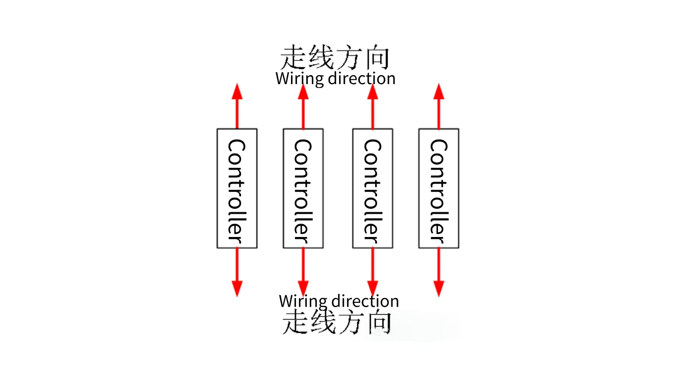
If horizontal space is insufficient, vertical arrangement can be considered, provided the first point's requirements are met. In such layouts, it is important to ensure that the controller's nameplate, status indicators, and other visual elements are easily observable for future use and maintenance. This arrangement is particularly suitable for controllers with all output, indicators, and fastening terminals on a single surface and that use quick-connect terminals.
However, some controllers have dual mounting surfaces. Opting for a smaller mounting surface may reduce the heat transfer area, so the impact of this change on heat dissipation must be considered carefully.

3. Installation Surface Treatment and Heat Dissipation Considerations
Most controller heat sinks are made of aluminum and may take the form of flat plates, fins, or fins with cooling fans. For flat heat sinks, the installation surface often requires polishing and cannot be mounted directly on painted surfaces (or should follow the manufacturer's recommendations). During installation, both the mounting surface and the controller base should be evenly coated with thermal paste or equipped with thermal conductive materials like silicone pads matching the base area to facilitate heat dissipation, especially for high-power controllers.
If the heat sink has a fan, ensure it is powered and operational for effective cooling. Regardless of the controller's power rating, all fastening screws must be installed and tightened as required, with no missing screws, improper tightening, or debris between the controller base and the mounting surface.
Control signal circuits, main circuits, and other high-current circuits must also be securely connected and fastened to prevent damage or malfunctions caused by cable tension or movement within the AGV. After every disassembly and reassembly, ensure that all connections are securely tightened and fixed.
Summary
This article provides an overview of the layout and installation considerations for controllers in AGVs. Always refer to the controller manual for installation guidelines, as manufacturers' instructions are typically suitable for most operating environments. At the same time, adapt flexibly to specific situations instead of rigidly following instructions. For compact electrical control boxes with high-power heat-generating equipment, adding convection cooling holes or fans is recommended for faster heat dissipation.
If the controller uses RS232 or 485 interfaces without specialized terminals for debugging, consider routing the communication lines to general-purpose terminals. For example, extend the RS232 port to a DB9 terminal to facilitate future debugging and maintenance tasks.


