

An AGV or AMR project rarely goes off track overnight. More often, the problems begin during the site survey.
A fleet size is estimated without calculating peak material flow. Aisle widths are based on verbal descriptions rather than actual measurements. Load handling requirements are unclear, and system integration or acceptance criteria are left until the implementation stage.
These gaps may seem minor during planning, but they can lead to traffic congestion, insufficient vehicle capacity, unexpected integration costs, and delayed commissioning.
A structured site survey helps engineering teams identify these risks before equipment selection and system design begin. It provides the foundation for choosing the right vehicle configuration, planning AGV drive systems, optimizing traffic flow, and establishing measurable project requirements.
This guide covers eight essential areas of an AGV/AMR site survey, from handling demand and material characteristics to system integration, commissioning, and final acceptance.
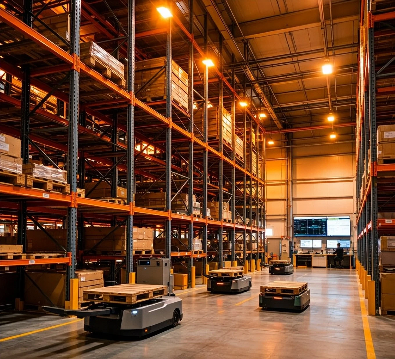
1. Calculate Handling Demand Before Determining Fleet Size
One of the most common mistakes in AGV/AMR project planning is accepting the customer's estimated vehicle quantity without verifying the actual workload.
The required fleet size should be calculated from handling demand, travel cycles, and operational constraints rather than from an initial guess.
Start by collecting the following information:
Material pickup and delivery locations
Material type and quantity per trip
Peak-period handling demand, measured in trips per hour
Average travel distance and travel time
Pickup, drop-off, and docking time
Empty-return requirements
Shift schedules, operating hours, and charging arrangements
A preliminary fleet-size estimate can be calculated using:
Theoretical fleet size = Peak handling demand × Average cycle time
When demand is expressed in trips per hour and cycle time in hours, the result represents the theoretical number of vehicles required to meet that demand.
The average cycle time should include loaded travel, pickup and drop-off operations, empty travel, and other relevant delays. A practical estimate must also account for traffic congestion, charging, and operational variability.
For preliminary planning, an additional capacity allowance of approximately 15–30% may be considered. This is a starting assumption, not a universal rule. The final fleet size should be validated against the actual workflow, peak demand, vehicle availability, and simulation results.
Key takeaway: Calculate the workload first, estimate the fleet size second, and validate the result before finalizing the proposal.
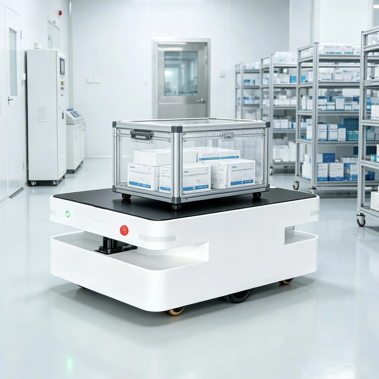
2. Understand the Materials Before Selecting the Vehicle
Material characteristics directly affect vehicle type, payload requirements, load-handling mechanisms, and drive system configuration.
A survey should document more than the material name. At a minimum, record:
Unit weight: Minimum, typical, and maximum weight
Load per trip: Total payload, including the carrier where applicable
Dimensions: Length, width, height, and any overhanging sections
Carrier type: Pallets, totes, cartons, stillages, or custom fixtures
Load stability: Stacking conditions, center of gravity, and tipping risks
Special requirements: Fragile goods, ESD protection, cleanroom operation, low temperatures, or hazardous environments
Transfer method: Underride lifting, fork handling, towing, conveyor transfer, or other docking mechanisms
Docking requirements: Transfer height, alignment tolerance, and interface conditions
Mixed pallet sizes or inconsistent carriers can complicate automatic pickup and delivery. They may require adjustable handling mechanisms or multiple vehicle configurations.
Heavy loads, unusual dimensions, and special operating environments also affect vehicle structure, wheel loading, motor sizing, braking requirements, and safety provisions.
For AGV/AMR projects involving heavy loads or demanding duty cycles, these details should be confirmed before selecting the drive wheel, motor, and transmission configuration.
3. Map Every Material Flow and Measure the Actual Cycle Time
A reliable site survey needs a complete task list rather than a few representative transport routes.
Document each material flow using a consistent format:
Pickup point → Destination → Material → Quantity per trip → Frequency → Return requirement
Include all relevant routes, including production-line replenishment, finished-goods transfer, empty-pallet return, waste collection, and other recurring movements.
What should be measured?
Production takt and material replenishment frequency
Peak and average handling demand
Travel distance and estimated cycle time for each task
Pickup and drop-off duration
Shift patterns and effective operating hours
Traffic peaks and overlapping transport routes
Empty-carrier return frequency and destinations
Buffer locations and temporary storage capacity
Empty returns deserve particular attention. Empty pallets and containers still occupy vehicle capacity and aisle space. If loaded and empty vehicles share the same routes, traffic conflicts can reduce the actual throughput of the system.
The survey should also clarify how the AGV or AMR interacts with production equipment. Does it dock manually, align with a conveyor, lift a fixture, or exchange signals with a PLC? Are elevators, automatic doors, roller conveyors, or lifting mechanisms involved?
These requirements influence docking accuracy, control logic, commissioning time, and the interfaces needed for unattended operation.
4. Measure the Site: Aisle Width, Floor Conditions, and Safety
Never finalize a vehicle layout based solely on the statement that an aisle is wide enough.
Actual site dimensions determine whether a vehicle can travel, turn, dock, and maneuver safely under real operating conditions.
Use appropriate measuring equipment and record the narrowest or most restrictive locations. Photographs and annotated layout drawings make the findings easier to verify.
Essential environmental checks
Space and access
Main aisle and branch aisle widths
Doorway clear widths and heights
Turning areas and docking clearances
Elevator dimensions, rated capacity, and availability in multilevel facilities
Floor and operating conditions
Floor material, flatness, and level changes
Ramp gradients and lengths
Floor load capacity
Oil, water, dust, trenches, and floor-cover conditions
Charging station locations and available electrical supply
Traffic and safety
Pedestrian and forklift traffic
Crossing points, blind corners, and congested areas
Required safety zones and emergency access
Applicable site safety rules and operating restrictions
Environmental and communication conditions
Temperature, humidity, and cold-storage requirements
Cleanroom or explosion-protection requirements
Strong light, reflective surfaces, and glass partitions where relevant to the navigation technology
Wi-Fi coverage, signal dead zones, and network infrastructure
Environmental conditions can affect wheel traction, localization performance, obstacle detection, and communication reliability. For example, slippery floors may compromise traction, while reflective surfaces or changing lighting can affect certain vision-based systems.
The survey should identify these conditions before the navigation method, drive configuration, and safety strategy are finalized.
5. Match Vehicle Type, Navigation, and Drive Configuration to the Application
The most advanced technology is not necessarily the best solution. Equipment should be selected according to payload, material handling requirements, aisle constraints, positioning accuracy, operating environment, and total system cost.
Common AGV/AMR vehicle types
| Vehicle type | Typical application |
|---|---|
| Underride lifting AGV/AMR | Transporting pallets, stillages, and loads from beneath |
| Pallet-handling robot | Automated pallet pickup and transfer |
| Autonomous forklift | Pallet transport, stacking, and warehouse operations |
| Very-narrow-aisle vehicle | High-density storage with restricted aisle space |
| Omnidirectional mobile robot | Applications requiring lateral movement or maneuverability in confined spaces |
| Tote-handling robot | Bin and carton transport, storage, and goods-to-person workflows |
The final selection must also consider the vehicle's load capacity, dimensions, turning radius, transfer height, and required operating speed.
Select a navigation method that fits the site
Common navigation options include magnetic guidance, QR-code navigation, LiDAR SLAM, vision-based navigation, and hybrid approaches.
When comparing them, consider:
Required positioning accuracy
Whether routes are fixed or frequently modified
Environmental lighting and reflective surfaces
Obstacle detection and avoidance requirements
Installation and maintenance costs
Future layout changes and expansion plans
Pedestrian-vehicle mixed traffic requires a carefully engineered safety strategy. Whether 3D obstacle detection is necessary depends on the operating environment, hazard assessment, and applicable safety requirements; it should not be treated as a universal substitute for a complete safety design.
Verify the drive system early
The drive system is a critical part of vehicle performance. It affects traction, acceleration, steering, maneuverability, positioning, and load-handling stability.
During the survey, confirm:
Total vehicle mass and maximum payload
Required travel speed and acceleration
Floor conditions, gradients, and traction requirements
Turning radius and available maneuvering space
Duty cycle and expected operating hours
Required steering method and motion control
Braking and safety requirements
Available power supply and battery voltage
Mechanical mounting space and controller compatibility
These parameters provide the basis for evaluating AGV drive wheels, drive axles, servo motors, and motion controllers.
For example, a heavy-duty transport vehicle operating on long routes may have different torque and thermal requirements from a compact AMR working in a confined warehouse. A vehicle requiring precise steering and positioning may also need a different drive configuration from one designed primarily for straight-line transport.
Plutools provides AGV/AMR drive components and motion-control products for mobile robot applications. Matching these components to the vehicle's actual operating conditions helps establish a more reliable foundation for system integration.
6. Confirm Fleet Management and System Integration Requirements
A vehicle that moves correctly on its own is not necessarily ready to operate as part of a complete intralogistics system.
The site survey should identify the existing software, automation equipment, and communication interfaces that the AGV/AMR system must work with.
Fleet management requirements
Current vehicle quantity and planned expansion
Single-zone or multi-zone operation
Traffic control and route reservation
Task assignment and priority rules
Congestion management and charging schedules
Monitoring dashboards, alarms, and reporting requirements
System integration requirements
WMS, WCS, MES, or ERP integration
Existing software vendors and version information
Available interface documentation and communication protocols
PLC connections to production equipment
Automatic doors, elevators, and conveyor interfaces
Network architecture and isolated network requirements
On-premises, cloud, or hybrid deployment
Customer IT support and integration responsibilities
For each interface, document the responsible party, expected data exchange, triggering conditions, error-handling logic, and testing requirements.
Unclear interface responsibilities are a common source of schedule delays. Confirming them during the survey makes it easier to define the project scope and identify additional development work before commissioning begins.
7. Plan Simulation, Commissioning, Training, and Trial Operation
When sufficient data is available, simulation or a small-scale pilot can help identify problems before full deployment.
The analysis should focus on:
Fleet size and peak throughput
Aisle congestion and route conflicts
Pickup and drop-off cycle times
Traffic rules and task assignment
Charging station capacity and scheduling
Bottlenecks at elevators, doors, and production interfaces
Simulation results should be checked against real site measurements and realistic operating assumptions. They are a planning tool, not a replacement for on-site validation.
Prepare the installation plan
Confirm the construction window, production shutdown requirements, permitted working hours, power supply, network cabling, site access procedures, and safety restrictions.
A staged commissioning process is recommended:
Single-vehicle testing: Verify movement, steering, braking, navigation, docking, and basic safety functions.
Multi-vehicle testing: Verify traffic control, task allocation, charging, and congestion handling.
System integration testing: Verify communication with production equipment, warehouse systems, elevators, and other interfaces.
Trial operation: Evaluate performance under representative production conditions.
A trial period of 14 days or longer may be appropriate for some projects, but the actual duration should be agreed upon according to operational risk and customer requirements.
Before trial operation begins, define how faults will be recorded, how alarms will be handled, how manual recovery will work, and who is responsible for restoring normal operation.
Operator and maintenance training should also be planned in advance. Confirm the number of trainees, training materials, maintenance procedures, assessment requirements, and arrangements for future staff turnover.
8. Define Acceptance Criteria, Deliverables, and Project Risks
Acceptance criteria should be agreed upon before implementation and documented in the contract or an approved technical specification.
Avoid vague requirements such as "stable operation" or "high efficiency." Use measurable indicators with clearly defined test conditions.
| Acceptance item | What to define |
|---|---|
| Handling throughput | Required pallets or loads per hour |
| Positioning accuracy | Permitted positioning error in millimeters |
| System availability | Target availability and calculation method |
| Failure rate | Definition of failure and measurement period |
| Repair time | Target recovery time and exclusions |
| Manual intervention | Permitted frequency under specified conditions |
| Task completion rate | Required completion percentage and reporting method |
| Safety performance | Applicable safety requirements and incident criteria |
| Interface accuracy | Data consistency and successful transaction requirements |
The acceptance method matters as much as the target. Specify the test duration, operating conditions, data source, exclusions, and responsible parties. For instance, a throughput target should state whether it applies to peak demand, sustained operation, or a defined test scenario.
Confirm the required project deliverables
Depending on the agreed scope, deliverables may include:
Equipment layout and installation drawings
Operating and maintenance manuals
Electrical drawings and interface documentation
Spare parts lists and maintenance schedules
Software configuration and system documentation
Training records
Trial-operation reports and acceptance documentation
Fault diagnosis and recovery procedures
Commercial terms should also be clarified, including warranty coverage, after-sales response times, remote support, on-site service, spare parts availability, and software updates where applicable.
Finally, maintain a project risk register. Record budget approval, required go-live dates, site renovation plans, production-line relocation, existing system replacement, decision-making responsibilities, certification requirements, and unresolved customer requests.
Each significant risk should have a rating, a responsible person, a mitigation plan, and a target resolution date.
AGV/AMR Site Survey Checklist: Final Review
Before completing the survey, verify that the following items have been addressed:
Material types, dimensions, maximum payload, and carrier specifications are documented.
All pickup and delivery routes, handling frequencies, and empty-return requirements are recorded.
Peak handling demand and realistic cycle times have been calculated.
Preliminary fleet size and charging requirements have been evaluated.
Aisles, doorways, floors, ramps, and docking areas have been measured.
Special environmental and safety requirements have been identified.
Vehicle type, navigation method, and drive configuration are supported by site data.
Fleet management, software interfaces, and IT responsibilities are confirmed.
Simulation, installation, commissioning, and training plans are defined.
Acceptance targets, test methods, and deliverables are documented.
Outstanding questions have assigned owners and confirmation dates.
The customer's project owner has reviewed the survey conclusions.
Conclusion: Build a Reliable AGV/AMR Project from the Ground Up
A successful AGV/AMR project begins with accurate information, not equipment selection alone.
Understanding the material flow, calculating peak handling demand, measuring the site, and confirming integration requirements helps engineering teams reduce uncertainty before it becomes expensive rework.
The same principle applies to drive components. Selecting AGV drive wheels, drive axles, servo motors, and motion controllers requires a clear understanding of the vehicle's payload, duty cycle, motion requirements, and operating environment.
At Plutools, we support AGV/AMR manufacturers and automation integrators with drive components and motion-control solutions for mobile robot applications. A well-defined site survey helps establish the technical requirements needed to evaluate suitable components and develop a reliable drive system.
Planning an AGV/AMR project? Contact Plutools to discuss your application, drive system requirements, and component selection needs.


